
 - Download Now (5 GALLON TANK MANUAL - AGITATED)")
Description
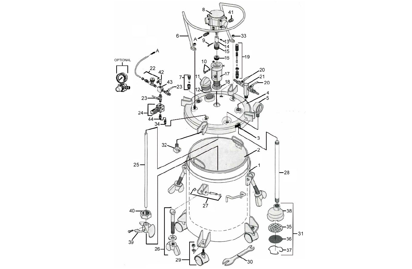
C.A. Technologies 5 Gallon Non-ASME Air Agitated Pressure Tank Parts Manual (51-503 / 51-504)
This page provides the official parts manual for the C.A. Technologies 5 Gallon (Non-ASME) Air Agitated Pressure Tank. Use this manual to view the parts diagram, confirm part numbers, and click through to order genuine replacement parts from CET.
Models Covered: 51-503 (Single Regulated) • 51-504 (Double Regulated)
Note: These tanks include air-powered agitation and are Non-ASME rated.
Download the PDF Parts Manual
Important Safety Note (Non-ASME Requirement)
Flammable Materials Warning: If this pressure tank is used for spraying flammable materials, the operator must not pressurize the tank more than 15 PSI to meet OSHA requirements for non-ASME pressure vessels.
- Max tank pressure: 80 PSI.
- Do not adjust the safety relief valve.
- Always ground the tank using 12 ga. wire.
- Relieve pressure completely before removing lid or fill cap.
- Oilless motor used – DO NOT OIL tank motors.
Shop These Tank Configurations
- 51-503 — 5 Gallon Pressure Tank (Single Regulated, Air Agitated)
- 51-504 — 5 Gallon Pressure Tank (Double Regulated, Air Agitated)
Order Replacement Parts (Click Part Numbers)
Below are the parts listed in the manual. Click any part number to open the matching product page on CET Store.
| Item | Part Number | Description |
|---|---|---|
| 1 | 51-526 | Tank Shell |
| — | 51-543-10 | Disposable Plastic Tank Liner (10 pk) |
| — | 51-527 | Optional Stainless Steel Tank Liner |
| 3 | 51-520 | Gasket (Available in 3 Pack) |
| 4 | 51-528 | Tank Lid Assembly |
| 5 | 52-58 | Pressure Gauge |
| 6 | 51-535 | Guard |
| 7 | 51-234 | Tank Vent Valve |
| 8 | 51-240 | Air Motor |
| 9 | 51-266 | Roll Pin |
| 10 | 51-264 | Screw & Nut 1/4-20 x 1" |
| 11 | 51-524 | Material Fill Cap |
| 12 | 51-522 | Seal Ring |
| 13 | 51-262 | Set Screw |
| 14 | 51-242 | Coupling |
| 15 | 51-288 | Guide |
| 16 | 51-289 | Chevron Packing Set |
| 17 | 51-287 | Air Motor Base |
| 18 | 51-245 | Seal Ring |
| 19 | 51-229 | Safety Relief Valve Assembly |
| 20 | 52-151 | Material Outlet Valve |
| 21 | 51-530 | Material Outlet Manifold |
| 22 | 51-247 | Speed Control Valve |
| 23 | 52-150 | Air Shut Off Valve |
| 24 | 52-6 | Air Regulator |
| 25 | 51-544 | Agitator Shaft |
| 26 | 51-236 | Eye Bolt Assembly |
| 27 | 51-233 | Pin Assembly |
| 28 | 51-523 | Fluid Pickup Tube |
| 29 | 51-224 | Caster |
| 30 | 51-225 | Wrench |
| 31 | 51-532 | Inlet Strainer Assembly |
| 32 | 51-237 | Air Flow Diffuser |
| 33 | 98-0115 | Nut 3/8-16 |
| 34 | 52-1 | Swivel Fitting |
| 35 | 51-549 | Inlet Screen Backup Plate |
| 36 | 51-542 | Inlet Screen |
| 37 | 51-519 | Inlet Screen Retaining Clip |
| 38 | 51-548 | Inlet Strainer Body |
| 39 | 51-246 | Propeller w/Bolt |
| 40 | 51-259 | Retaining Nut |
| 41 | 51-271 | Muffler |
| 42 | 51-268 | 90 Degree Elbow |
| 43 | 51-267 | 4-Way Union |
| 44 | 53-562 | 1/4 x 1/4 Nipple Fitting |
Regulator note: Single regulated tanks are supplied with one regulator; double regulated tanks include both fluid and air regulator assemblies.
Related Pressure Tank Manuals
Need Help Identifying a Part?
If you’re unsure which part you need for your 51-503 or 51-504 tank, contact CET with your model number and item number from the diagram.
")
 - Download Now (2.5 GALLON TANK AG MANUAL)")
 - Download Now (5 GALLON TANK MANUAL MIXER BOTTOM OUTLET)")

")