
")
Description
C.A. Technologies Bobcat Air Assist Airless Spray Gun — Parts Manual, Tip Chart & Fluid Flow Guide
The C.A. Technologies Bobcat is an air assist airless (AAA) spray gun that combines airless fluid pressure (350–1500 PSI) with a small volume of atomizing air at the cap — delivering finer atomization and finish quality than pure airless while maintaining the high transfer efficiency and tip-controlled pattern that airless systems are known for. Unlike conventional spray guns where air is the primary atomization driver, the Bobcat uses fluid pressure to break up the material and air to refine the pattern — making it well suited for high-production coating operations where finish quality and material throughput both matter. Air consumption at the gun is 3–5 CFM depending on regulator pressure, significantly lower than conventional gun setups. HVLP compliant at ≤18 PSI air at the gun handle. Distributed by Coating Equipment Technology. Call or text 586-210-0555 for setup guidance and tip selection before ordering.
Download the Bobcat Parts Manual (PDF)
Key Specs
At a Glance
| Gun Type | Air Assist Airless (AAA) |
| Max Fluid Pressure | 1500 PSI |
| Air Consumption (gun only) | ~3–5 CFM depending on regulator pressure — add pump CFM for total compressor requirement |
| HVLP Compliance | Yes — do not exceed 18 PSI air pressure at gun handle |
| Tip System | 36-XXX series — 21 standard tips from 0.007" to 0.021" orifice, 20° to 80° spray angle |
| Filter (standard) | 66-125 — 100 mesh. 66-124 60 mesh optional |
| Repair Kit — Soft Seals | 10-137 — all o-rings and seat |
| Repair Kit — Complete | 10-138 — soft seals plus air valve assembly (60-1320) and needle seal cartridge (66-330) |
| Trigger Safety | Activated when trigger pushed forward |
| Fan Control | Knob — CCW narrows fan; fully closed = maximum pattern width (set by tip selection) |
| Distributor | Coating Equipment Technology — 586-210-0555 — cetinc.com |
Tip Selection
Understanding Bobcat Tip Part Numbers
Bobcat tips use a 5-digit part number system: 36-XYY where X is the spray angle in tens of degrees and YY is the orifice size in thousandths of an inch. For example, 36-413 = 40° spray angle, 0.013" orifice, approximately 8" pattern. Choose orifice size based on material viscosity and flow rate requirements; choose spray angle based on part geometry and desired pattern width.
Available Tips
All 21 Standard Tips — Orifice, Angle & Pattern
| Part # | Orifice | Spray Angle | Approx. Pattern |
|---|---|---|---|
| 36-207 | 0.007" | 20° | 4" |
| 36-309 | 0.009" | 30° | 6" |
| 36-409 | 0.009" | 40° | 8" |
| 36-311 | 0.011" | 30° | 6" |
| 36-411 | 0.011" | 40° | 8" |
| 36-511 | 0.011" | 50° | 10" |
| 36-213 | 0.013" | 20° | 4" |
| 36-313 | 0.013" | 30° | 6" |
| 36-413 | 0.013" | 40° | 8" |
| 36-513 | 0.013" | 50° | 10" |
| 36-613 | 0.013" | 60° | 12" |
| 36-315 | 0.015" | 30° | 6" |
| 36-415 | 0.015" | 40° | 8" |
| 36-515 | 0.015" | 50° | 10" |
| 36-615 | 0.015" | 60° | 12" |
| 36-715 | 0.015" | 70° | 14" |
| 36-815 | 0.015" | 80° | 16" |
| 36-417 | 0.017" | 40° | 8" |
| 36-517 | 0.017" | 50° | 10" |
| 36-619 | 0.019" | 60° | 12" |
| 36-621 | 0.021" | 60° | 12" |
Pattern sizes are approximate and will vary with fluid pressure and material viscosity. Optional: 36-100 Tip Strainer. Also available: 36-XXX-F Opti-Tip variant. Call or text 586-210-0555 for tip selection guidance.
Fluid Flow Reference
Tip Flow Rate Chart — Fluid oz/min.
Values are approximate and will vary depending on actual material viscosity. Light materials flow faster than heavy materials at the same fluid pressure. Use this chart to match tip orifice to your required output rate.
| Tip Size | 350 PSI | 700 PSI | 1000 PSI | 1500 PSI | ||||
|---|---|---|---|---|---|---|---|---|
| Light | Heavy | Light | Heavy | Light | Heavy | Light | Heavy | |
| 0.007" | 3 | — | 4 | — | 5 | — | 6 | — |
| 0.009" | 5 | — | 8 | — | 9 | — | 11 | — |
| 0.011" | 8 | — | 11 | — | 13 | — | 16 | — |
| 0.013" | 10 | — | 14 | — | 17 | — | 21 | — |
| 0.015" | 13 | — | 18 | — | 22 | — | 27 | — |
| 0.017" | 17 | 13 | 24 | 18 | 29 | 22 | 35 | 27 |
| 0.019" | 21 | 16 | 30 | 23 | 36 | 27 | 44 | 33 |
| 0.021" | 27 | 21 | 38 | 29 | 45 | 35 | 56 | 43 |
— indicates data not available for that orifice/pressure/viscosity combination. Values are approximate and vary with actual material viscosity.
Air Requirements
Compressor Sizing — Gun + Pump
Total compressed air requirement for the Bobcat system is gun CFM + pump CFM. The gun draws approximately 3–5 CFM depending on regulator pressure. The pump (e.g., B14 AAA pump) draws additional CFM depending on fluid pressure and cycle rate. Size your compressor for the combined total.
Example from manual: Gun regulator at 25 PSI = ~3.5 CFM. Pump at 1000 PSI fluid pressure, 30 cycles/min = ~1.75 CFM. Total minimum compressor requirement: 3.5 + 1.75 = 5.25 CFM. Call or text 586-210-0555 to confirm compressor sizing for your specific pump and application before ordering.
Parts & Repair Kits
Complete Parts List — All Components
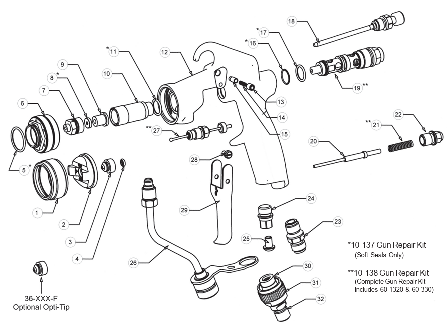
| Item | Part # | Description | Kit |
|---|---|---|---|
| 1 | 21-1001 | Air Cap Ring | |
| 2 | 26-101 | Air Cap | |
| 3 | 36-XXX | Fluid Tip — see tip table above | |
| 4 | 98-8007 | O-Ring (tip seal) | 10-137 |
| 4 | 36-100 | Tip Strainer (optional) | |
| 5 | 98-8019 | O-Ring (air cap adapter) | 10-137 |
| 6 | 66-103 | Air Cap Adapter | |
| 7 | 66-104 | Nozzle Body | |
| 8 | 66-105 | Seat | 10-137 |
| 9 | 66-110 | Seat Retainer | |
| 10 | 66-302 | Nozzle Carrier | |
| 11 | 98-8014 | O-Ring | 10-137 |
| 12 | 66-301 | Gun Body | |
| 13 | 98-0275 | Set Screw | |
| 14 | 66-310 | Spring (trigger safety) | |
| 15 | 66-313 | Pin, Trigger Safety | |
| 16 | 98-5125 | O-Ring | 10-137 |
| 17 | 98-5225 | O-Ring | 10-137 |
| 18 | 66-308 | Fan Control | |
| 19 | 60-1320 | Air Valve Assembly | 10-138 only |
| 20 | 66-337 | Push Rod | |
| 21 | 66-344 | Spring (fluid) | |
| 22 | 66-340 | Spring Cap | |
| 23 | 60-104 | Air Inlet Fitting | |
| 24 | 66-319 | Handle Plug | |
| 25 | 98-0186 | Screw | |
| 26 | 66-315 | Fluid Tube Assembly | |
| 27 | 66-330 | Needle Seal Cartridge | 10-138 only |
| 28 | 60-1315 | Trigger Pivot Screw | |
| 29 | 66-350 | Trigger | |
| 30 | 66-125 | Filter, 100 mesh (standard) | |
| 30 | 66-124 | Filter, 60 mesh (optional) | |
| 31 | 66-123 | Filter Retaining Nut | |
| 32 | 66-122 | Filter Housing, Lower |
10-137 Soft seals kit — items marked above 10-138 Complete kit — adds air valve assembly (60-1320) and needle seal cartridge (66-330)
Repair Kits
Which Repair Kit Do I Need?
Maintenance note: Complete gun disassembly is not recommended for normal cleaning. Do not soak the entire gun in solvent. Always relieve fluid pressure to 0 PSI before performing any maintenance. Call or text 586-210-0555 for maintenance guidance.
Bobcat Air Assist Airless Spray Gun — Parts Manual
Full exploded diagram, tip chart, fluid flow rates, air consumption data & all replacement part numbers
Download the Bobcat Parts Manual (PDF)Need Help Selecting Tips or Sizing Your System?
Contact CET’s technical support team with your material, fluid pressure, and pump model. We’ll confirm the right tip orifice, spray angle, and compressor requirement for your specific Bobcat setup. Call or text 586-210-0555.
")
")
")
")
")